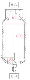
Geometrical data of
pressurizer is shown in the figures below.
The
pressurizer is subdivided into modules from 601 to 603, as shown in Figure
2.3.
In the joint between the pressurizer bottom and the pressurizer surge line end
there is the pressurizer surge nozzle. Inside the pressurizer surge nozzle there
is the screen component, as shown in Figure 2.4. The internal diameter of the surge line is 42.8 mm, while the external diameter
is 60.3 mm. The geometrical details of the heaters can be seen in Figure 2.6. In the pressurizer there are 12 electrical heaters with 4kW of power
each. The power capacity of the primary heaters is 12 kW, while the power of the
backup heaters is 36 kW.
2.4: Pressurizer Bottom Cutaway
Figure 2.5:
Pressurizer
2.6:
Pressurizer (heater rods)
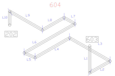
2.7: Modules
of Surge Line Piping
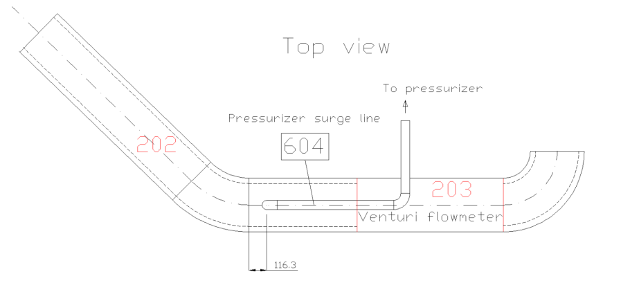
Figure 2.8: Geometrical Data of Pressurizer Insertion in Intact Loop Hot Leg